Apple PowerMac G5s came with either air cooling or liquid cooling. Many G5s died when the water coolers sprang a leak and poured water into the PSU housing. Most often the leaks were not from a failed pump, but often a seal in the CPU water block.
When you buy a dead G5 with a water cooler, I suggest that you do not throw away the cooling unit, but instead think about re-using the pump (the radiator could also be re-used, but many people do not like the idea of using aluminium radiators in water loops…..but that is another story).
Why re-use the pump? Well it is a Laing DDC unit which is pretty much an industry standard and new costs around £55.
Why don’t more people re-use the G5 pump? The answer to that is that the G5s had proprietary fixings in the form of different wiring, and a volume compensator. Also, people felt that re-using a component from a failed G5 may be a false economy.
On the economics side and the practicality side there is a good reason for refurbishing your pump with a new circuit board from the incredibly well priced DIYINHK (for DIY in Hong Kong) that you can track down via eBay and google. If you want to contact him then you can find him by his eBay user link: http://www.ebay.com/usr/diyinhk
DIYINHK make boards of various types and the one I am showing how to fit in this post is a $10 (including worldwide postage) item for incorporating a new Sanyo pump controller PCB into your Laing pump. As Google will tell you, the results are a seriously quiet water pump which is more efficient than the original G5 and the normal Laing DDC pumps and is also voltage speed controllable (by use of a fan controller or simple voltage reducing circuit).
As well as the board I am fitting here, he sells an 18W pump upgrade and a PWM speed adjustable upgrade too.
IF you are competent with a soldering iron, then it is worth a go. If you are not good with a soldering iron then I suggest you forget it – as this process is not for the impatient.
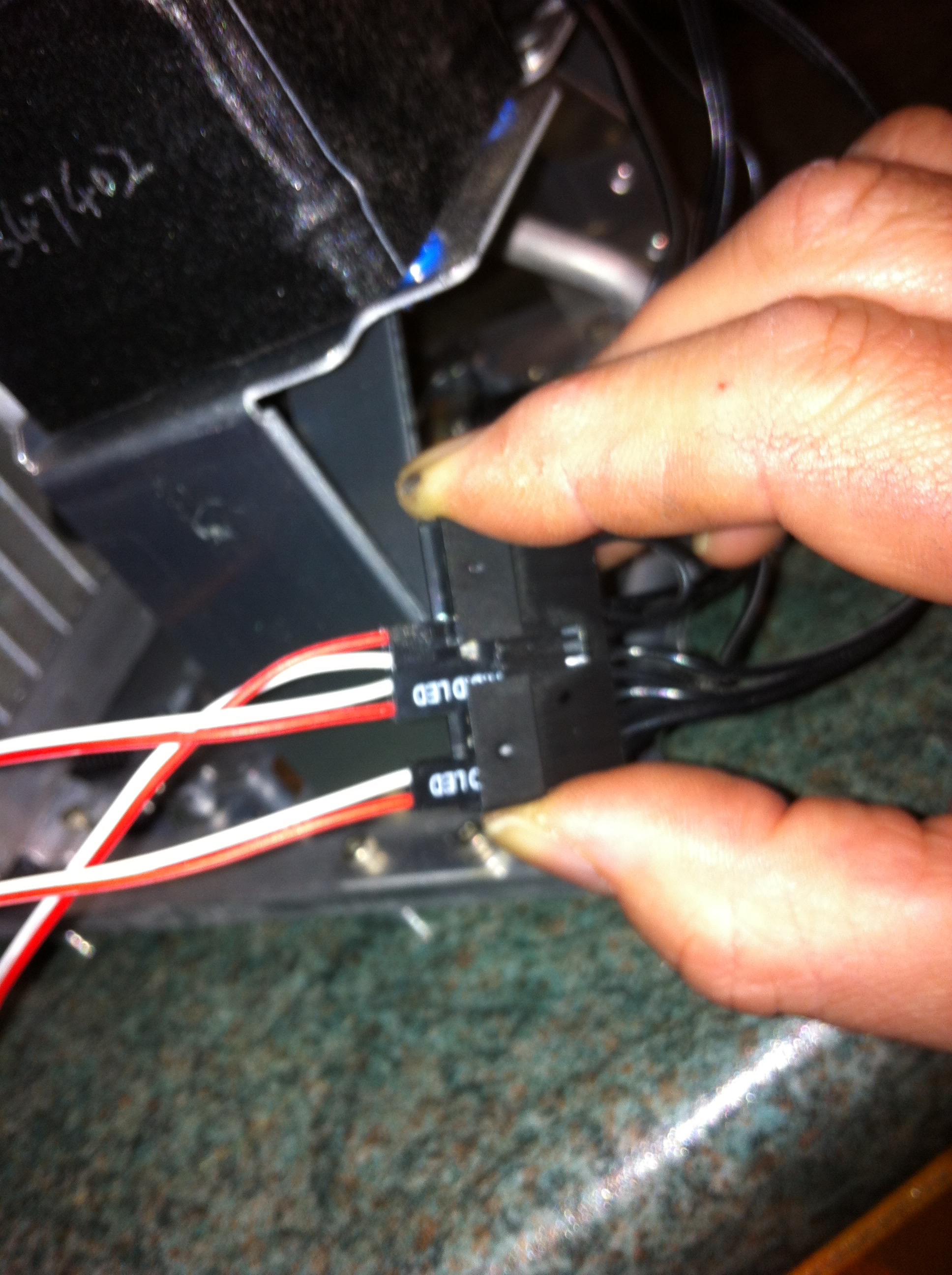
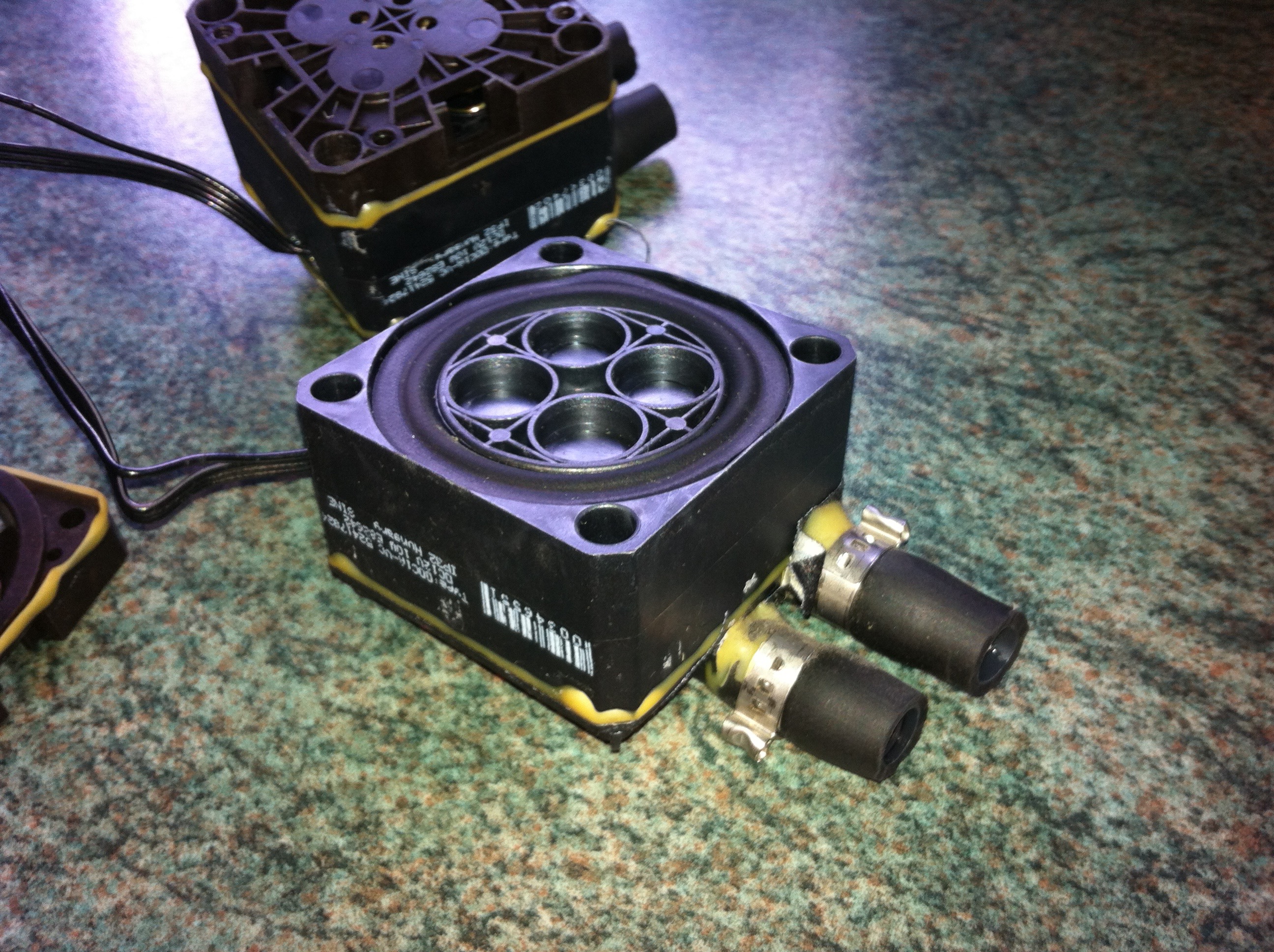
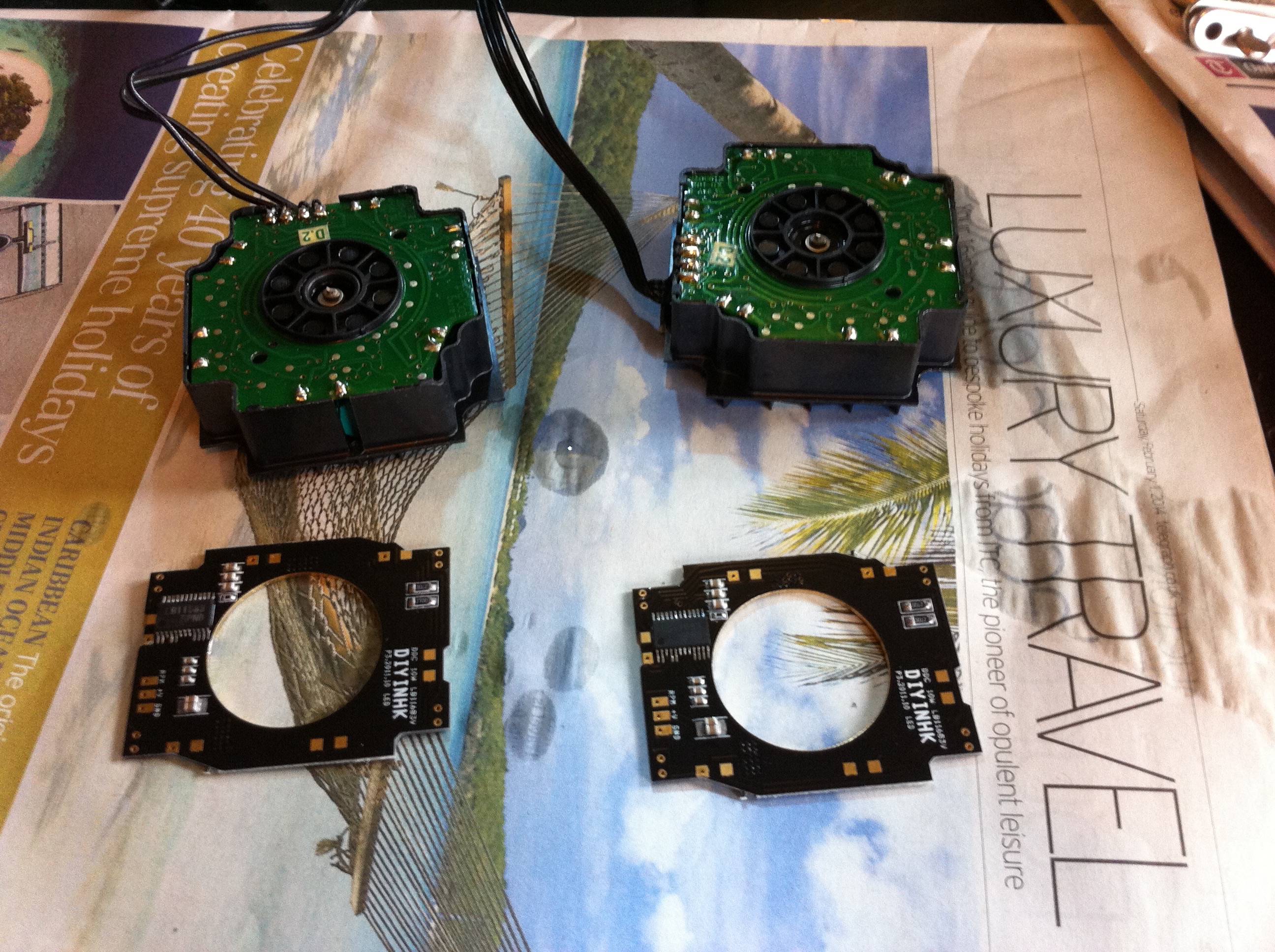
In these shots you see the original unit and me testing it to check if it functions. To do that you need to connect +12v to two points on each pump and ground to one point (the pump leads are: Ground, rpm, +12v and “Motor” (which needs 12v) on the large breakout plug you can see I used some spare front panel connector leads from a PC to jerry-rig the inputs.
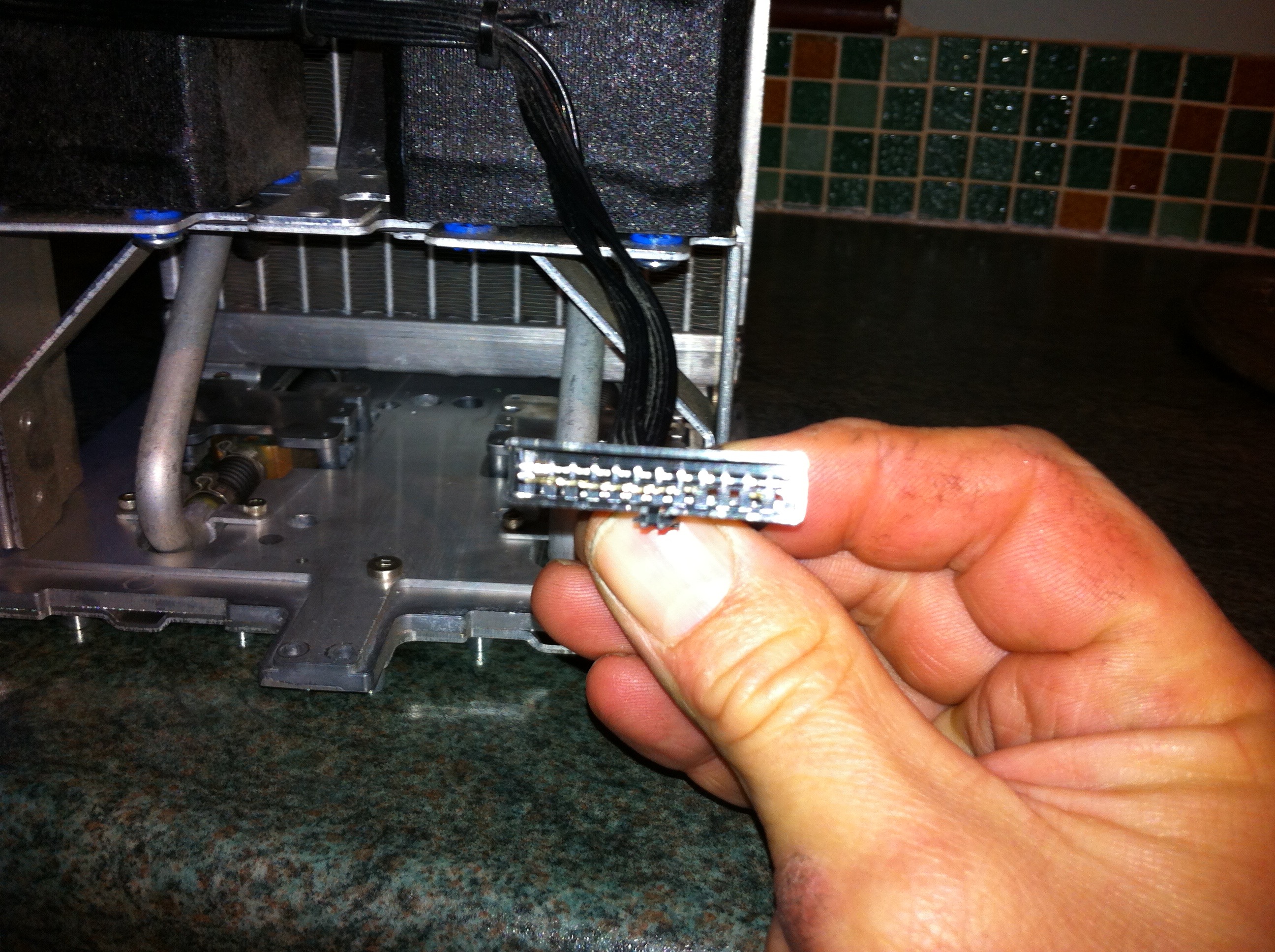
Both pumps sprang into a slightly noisy life, but obviously working, so I quickly disconnected, knowing that they should be good candidates for conversion.
In fact, even if the pumps did not work then it is still probably possible to do this conversion successfully as if the reason for failure was a component fault on the control PCB then this conversion will correct that……
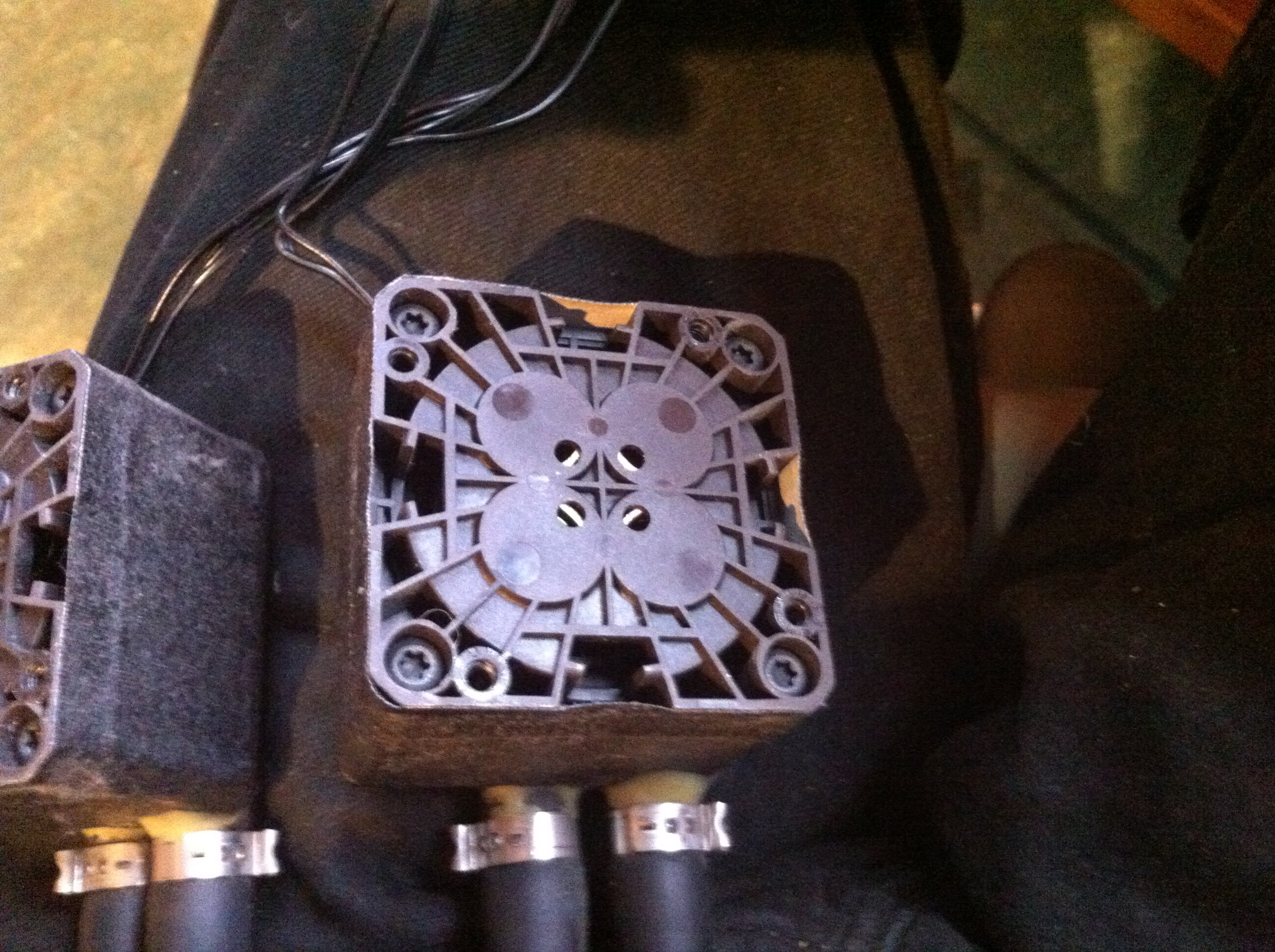
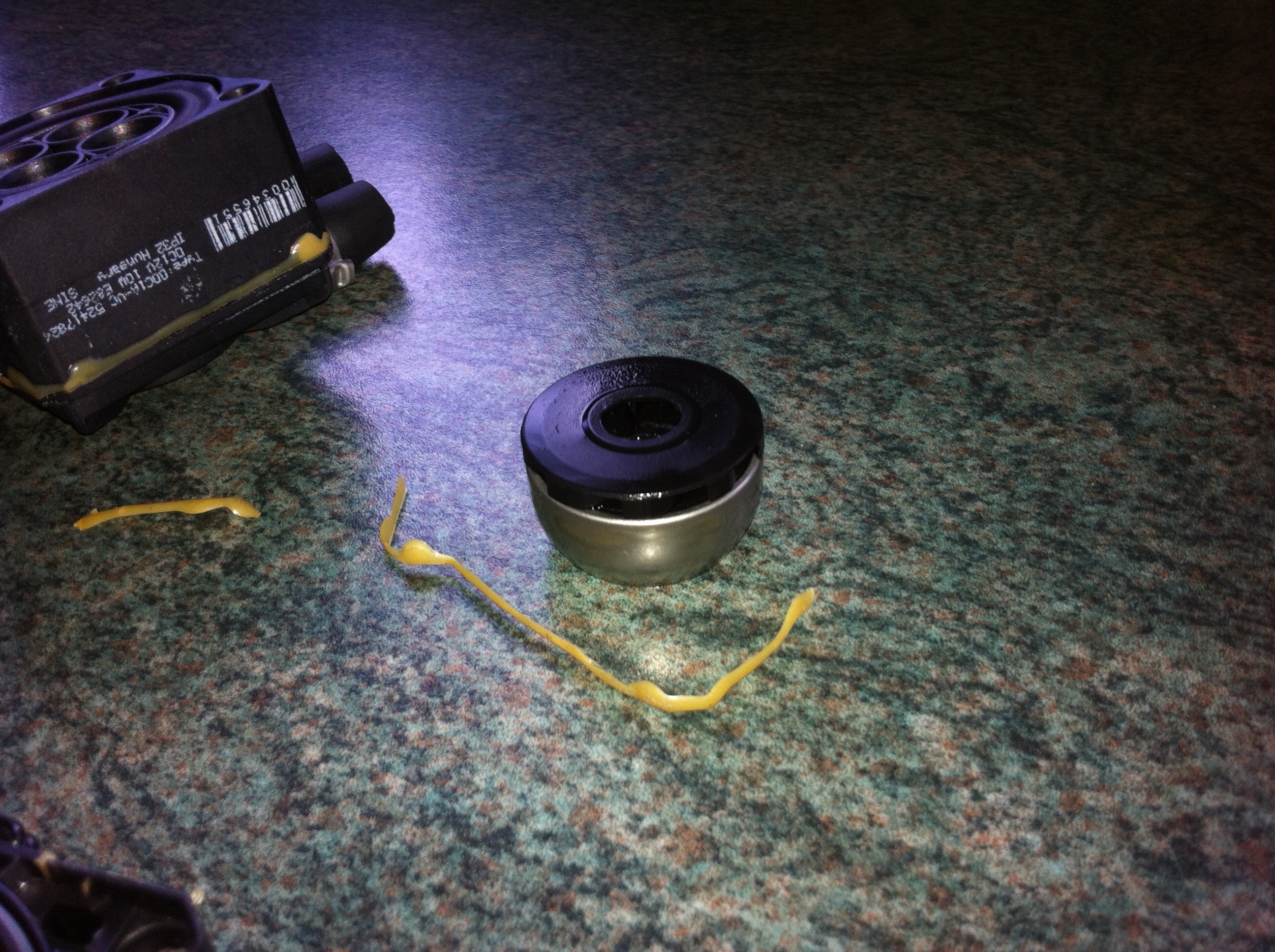
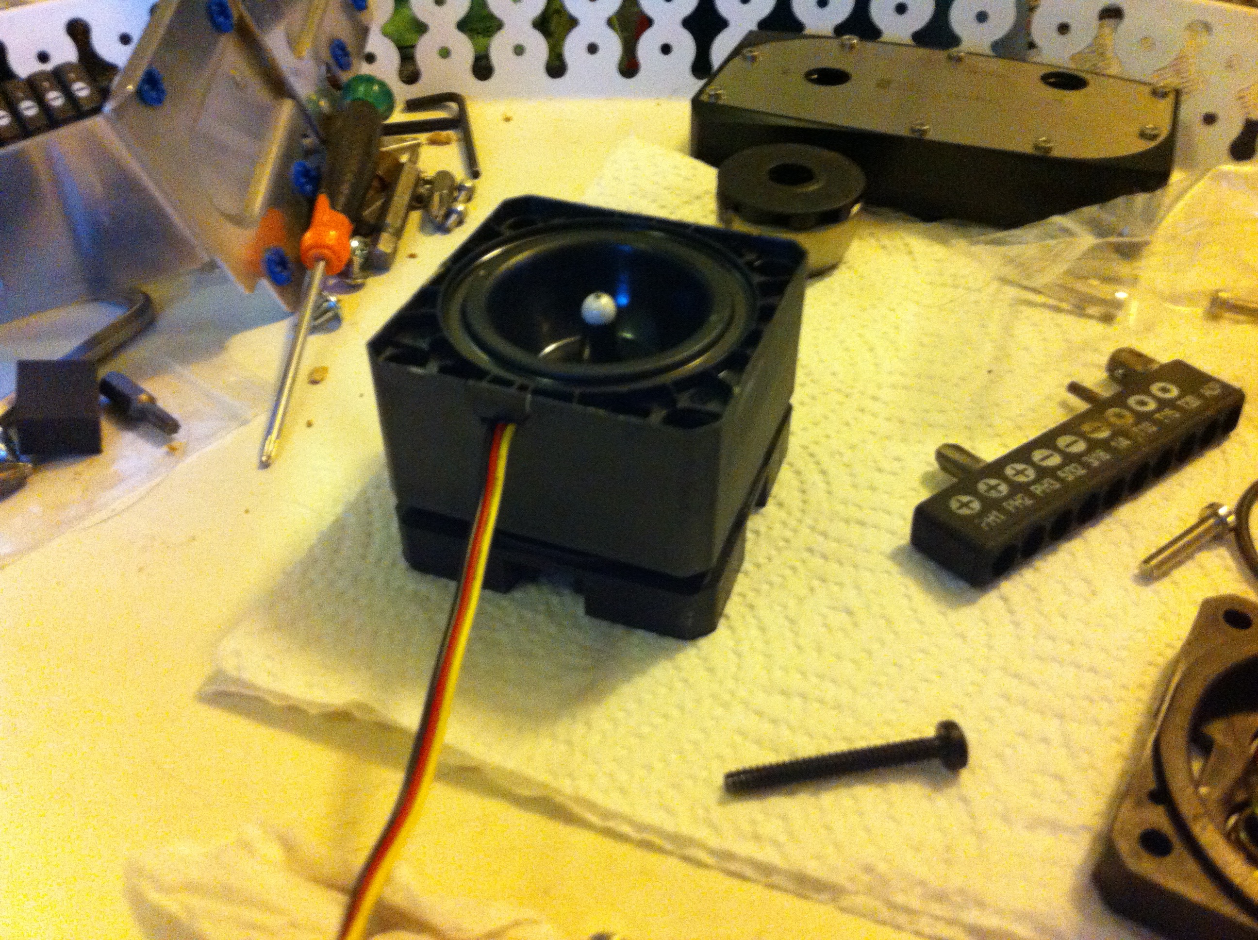
Here is the underside of the pump assembly and you need to undo the 4 Torx 20 screws to take the pump apart.
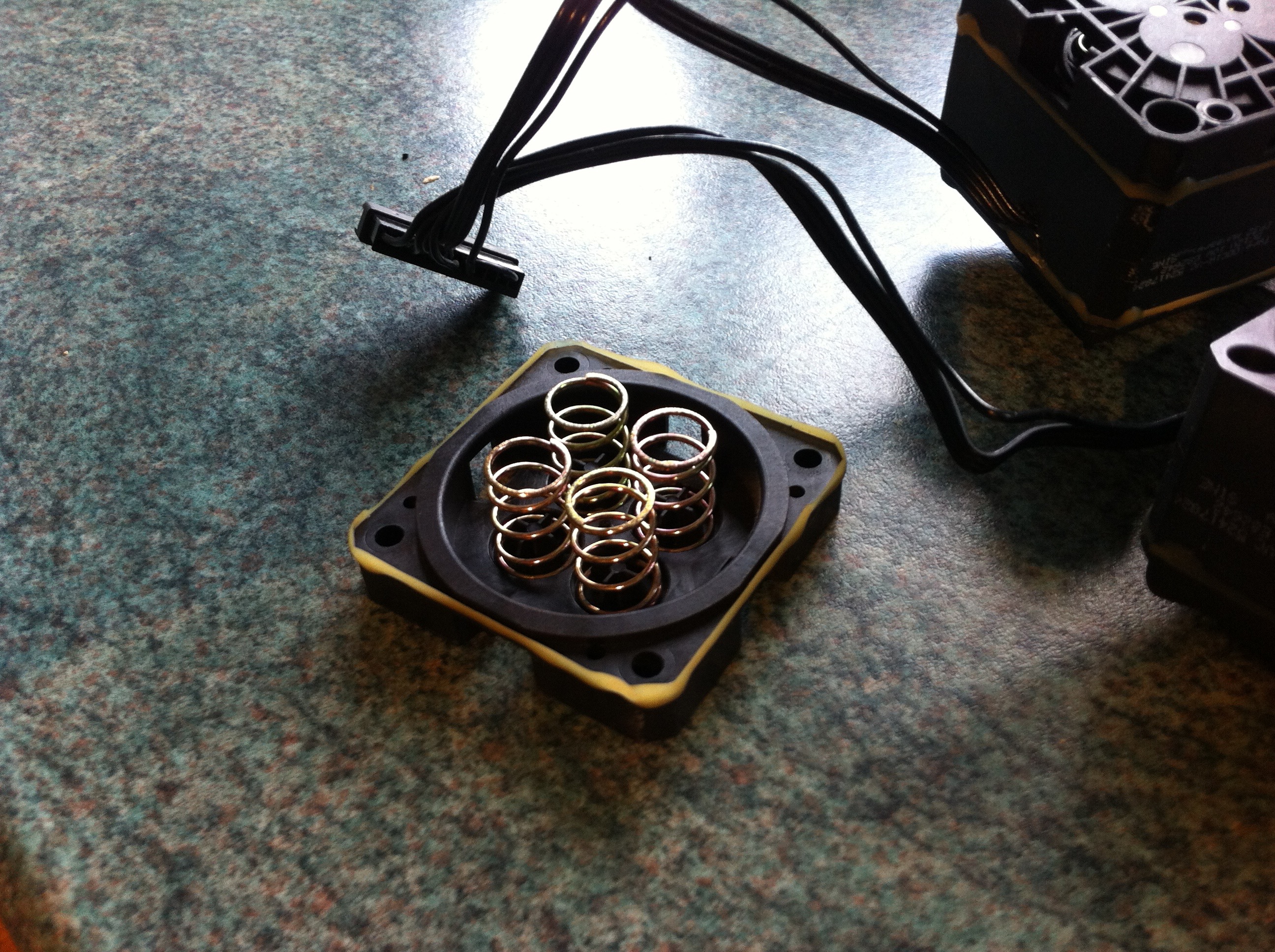
And here are some disassembly shots, note that the lower compartment is full of springs – this is the volume compensator module that Apple used in the G5 to account for the lack of a reservoir in their cooling loops:
The original control board of the pump exposed
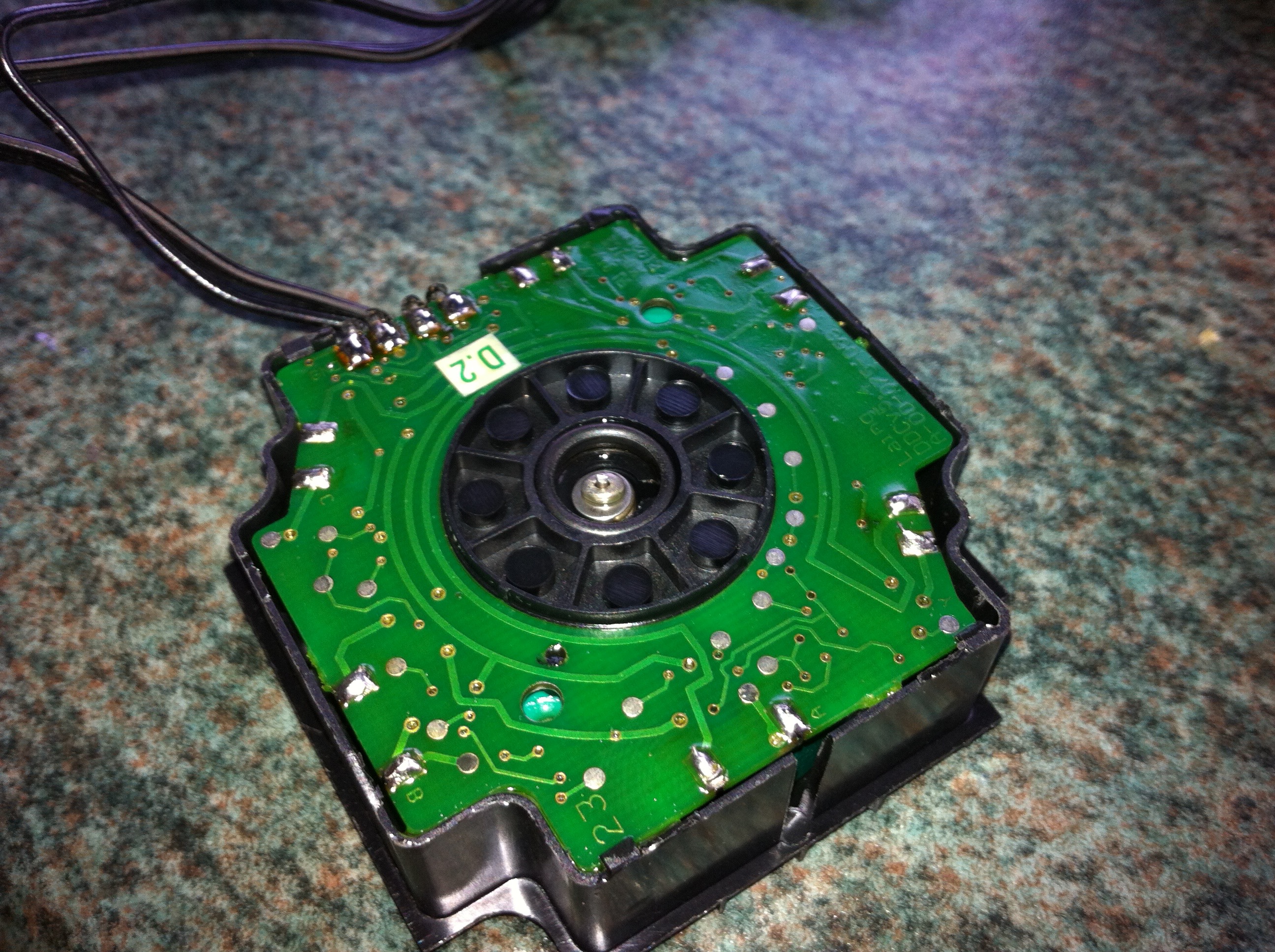
Here is a link to a video of the original PCB removal process:
Laing DDC pump PCB removal
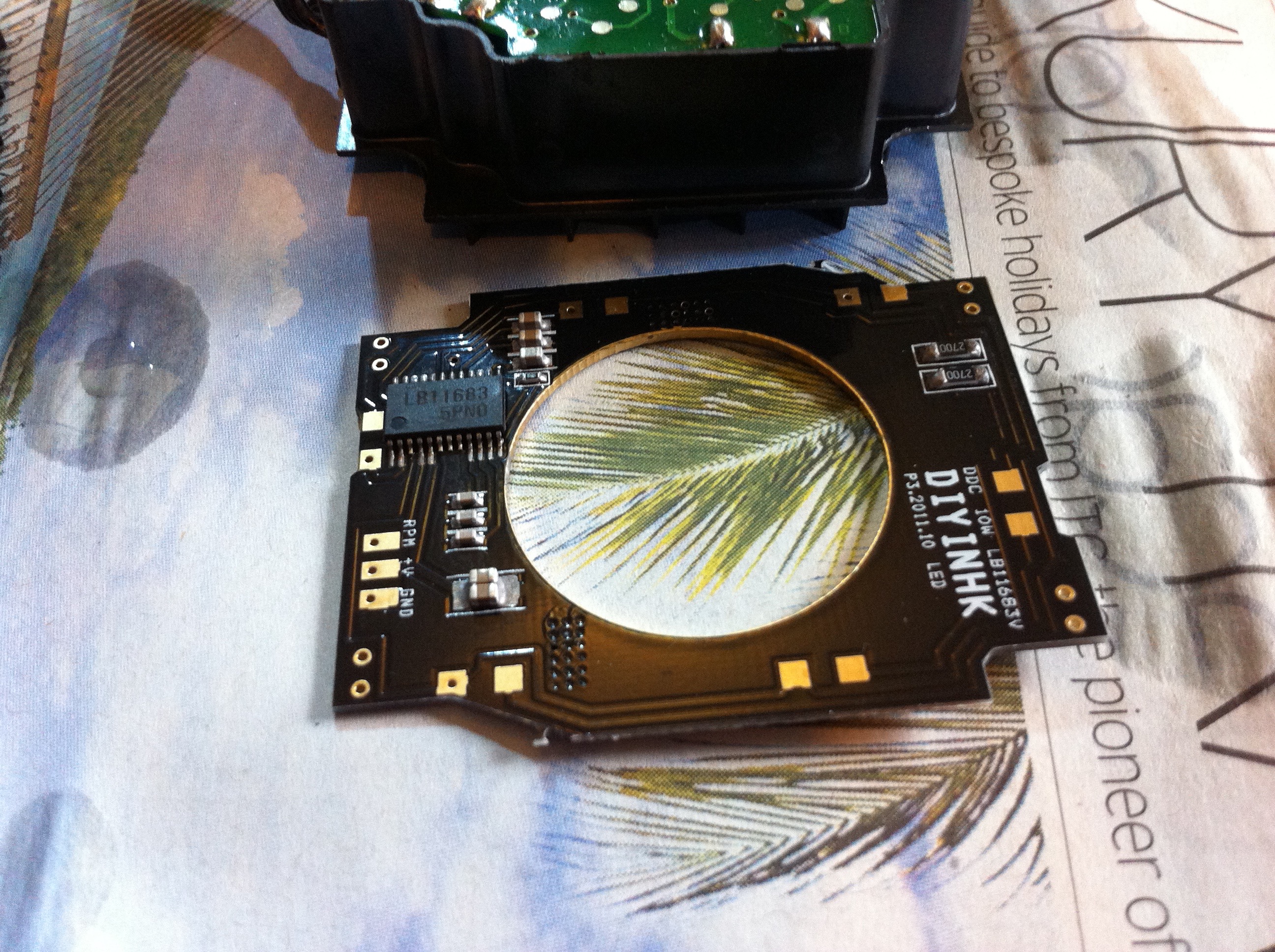
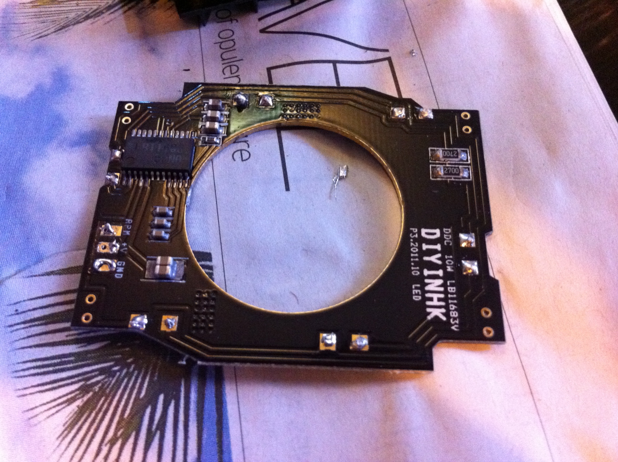
The replacement controller board has a Sanyo pump controller chip as used in the Swiftech pumps – it is quieter and more efficient than the original g5 control chip and enables easy voltage control of pump speed and reporting of pump speed to a fan controller.
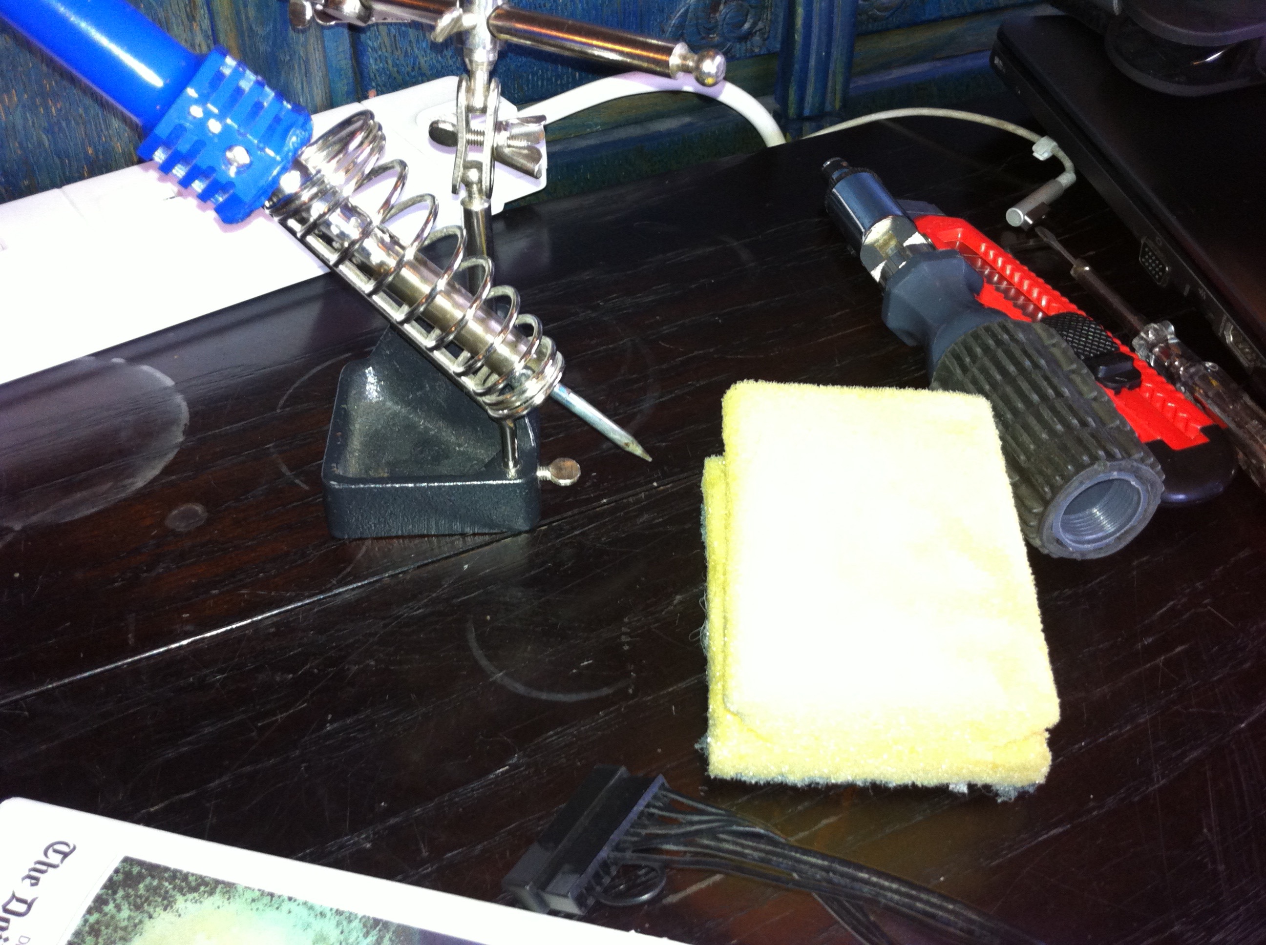
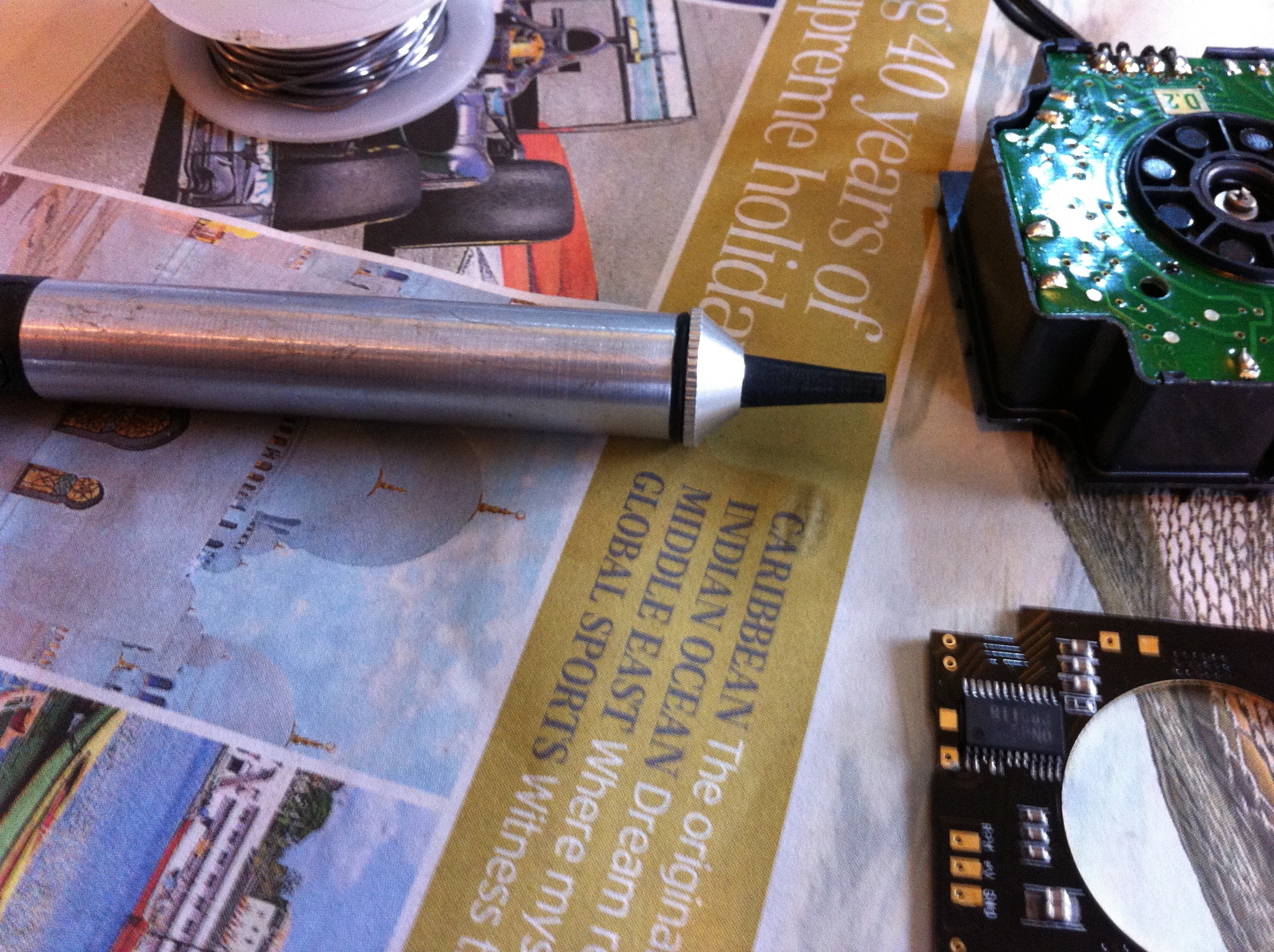
Recommended tools for the job are soldering iron (essential), wet sponge (to clean the solder from the iron), Torx 20 screwdriver (disassembly of pump), craft knife (to help in removing original stator coil wires from the PCB), solder removal pump (for doing initial de-soldering of the coil leads).
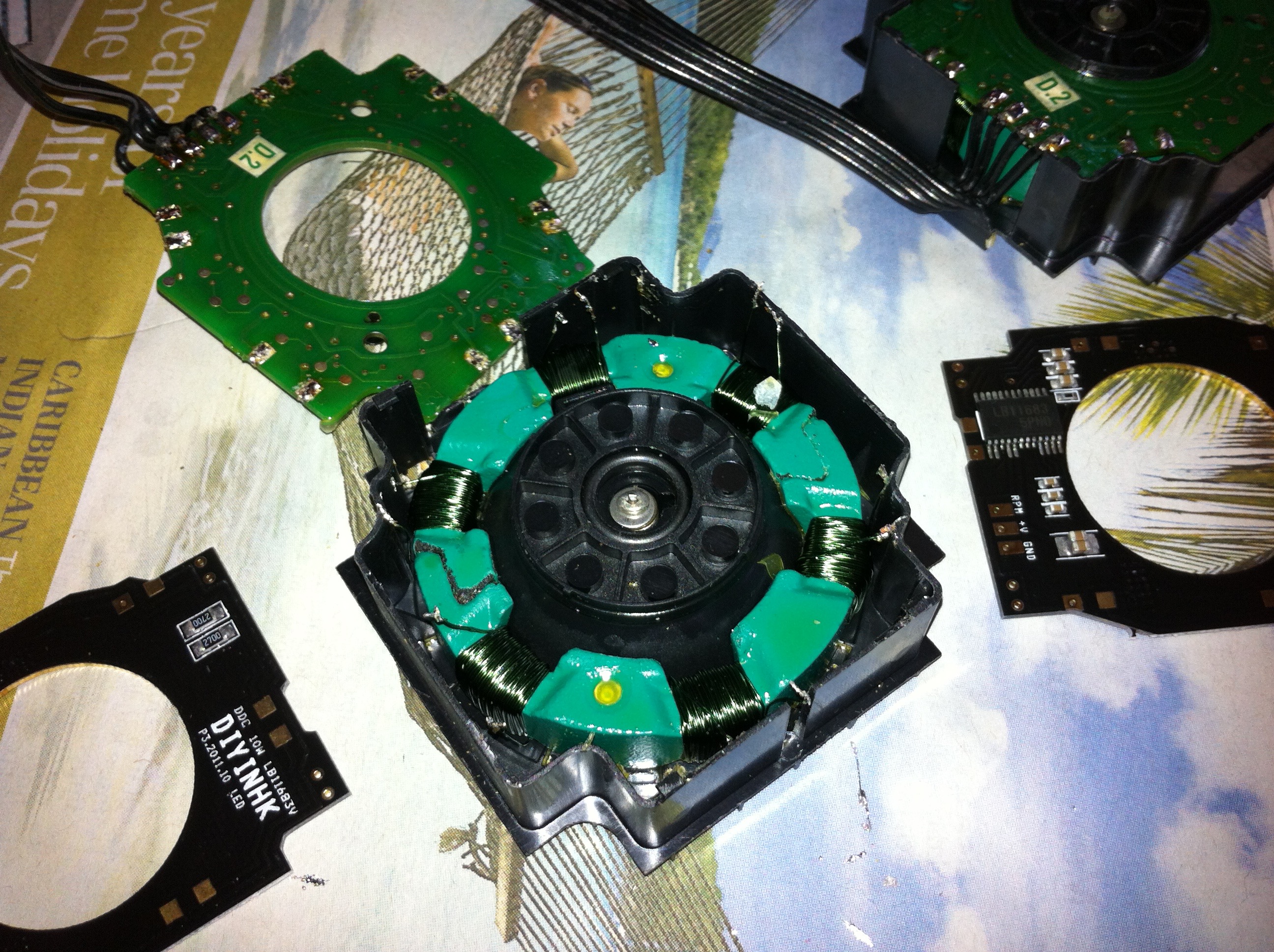
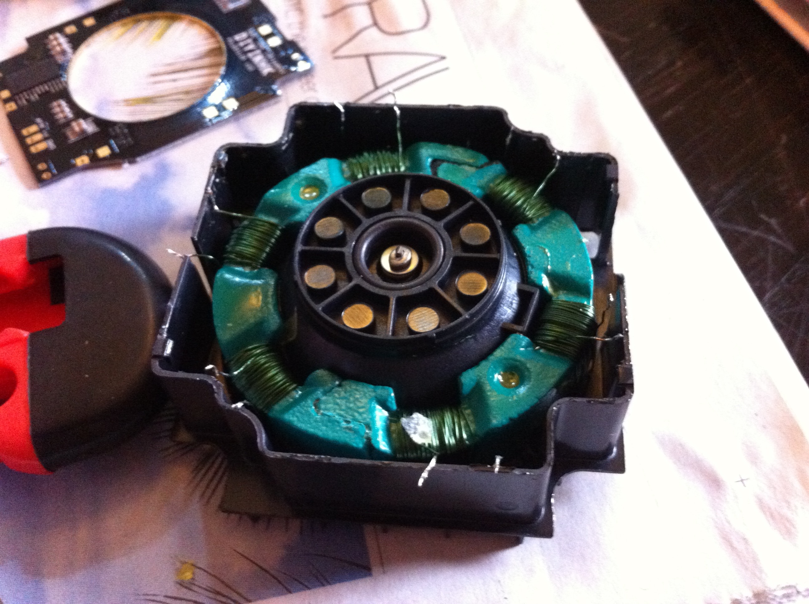
And here is the stator exposed, having removed the old controller PCB. If you have been very careful and lucky then you will not have broken any of the small stator coil windings! If you did break one or two then do not worry, but you will need to remove the stator from the housing, unwind the affected coil by one turn to get enough free material, scrape enamel of the new length and then reattach the stator into the original position WITH adhesive (this is essential – in contradiction to what I say in the next video – as I have found that if you do not stick it back in place then the pump will be very noisy as the stator can move and could potentially cause pump failure). This is one reason why I definitely advise you to take your time when de-soldering!!
Here is a link to my video of how to make good your mistake though if you do break a wire from the stator:
Before attaching the new controller board, I recommend that you pre-solder each of the pads to which you will be attaching the coil windings of the stator. Before you do that, clean the contact pads or scrape them lightly with a craft knife so that a clean surface is exposed – you will find them easier to solder to if you do this!
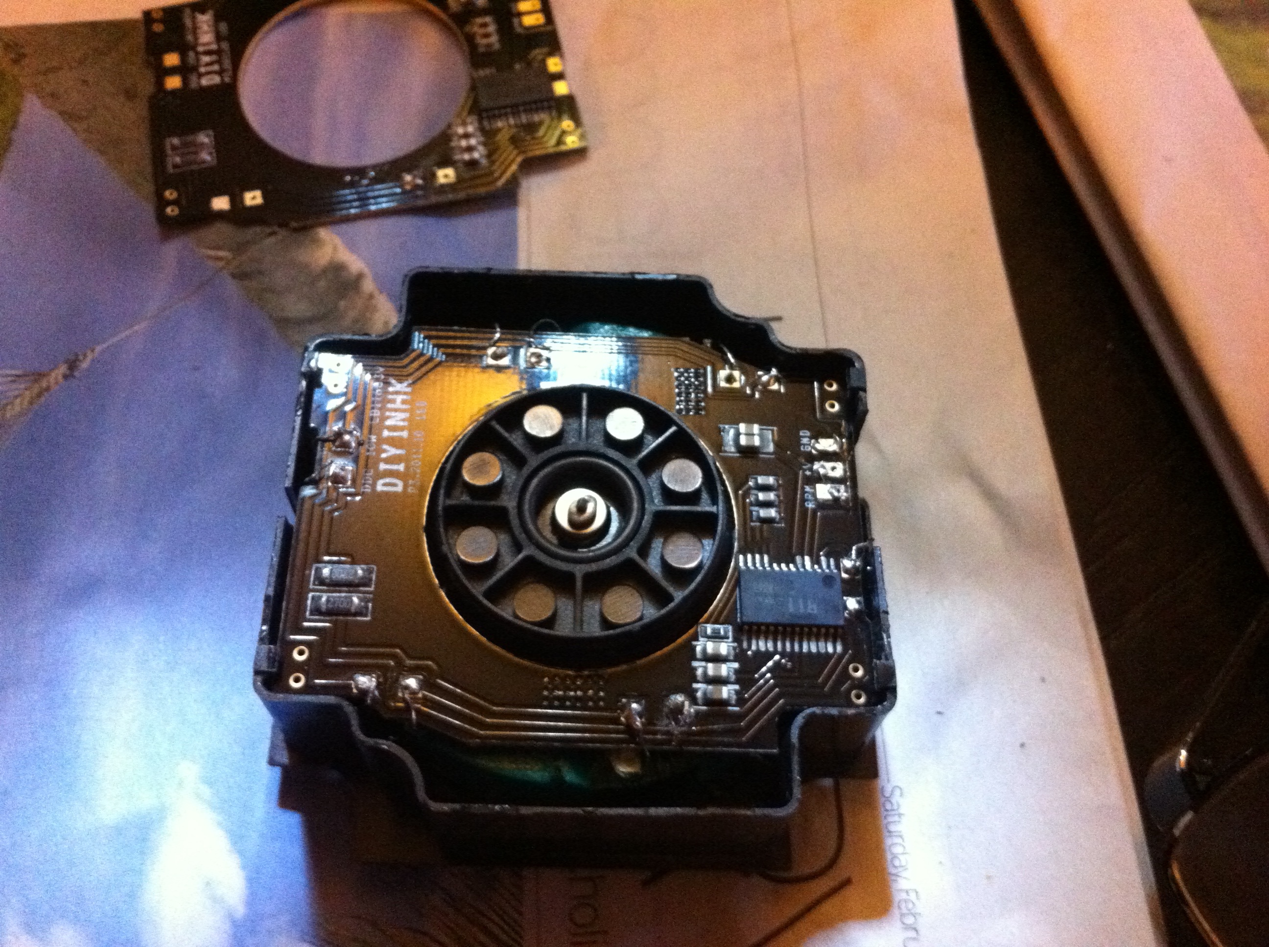
The controller board is placed so that the power connections are aligned to the gap in the pump housing and then the leads from each of the coils are positioned and soldered in to place.
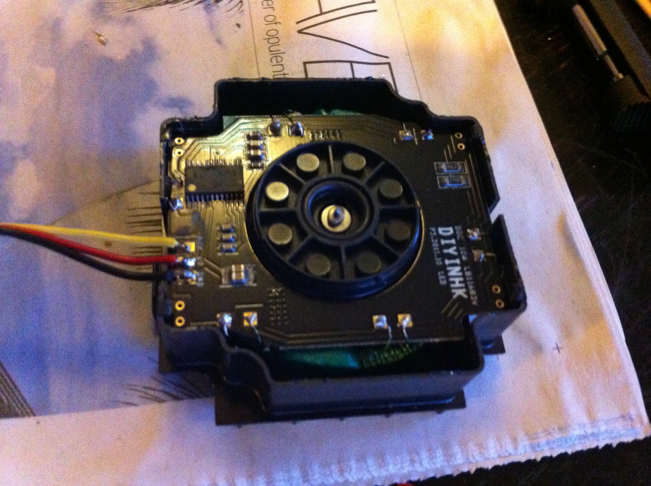
Now solder the 3 pin fan connector lead to the PCB
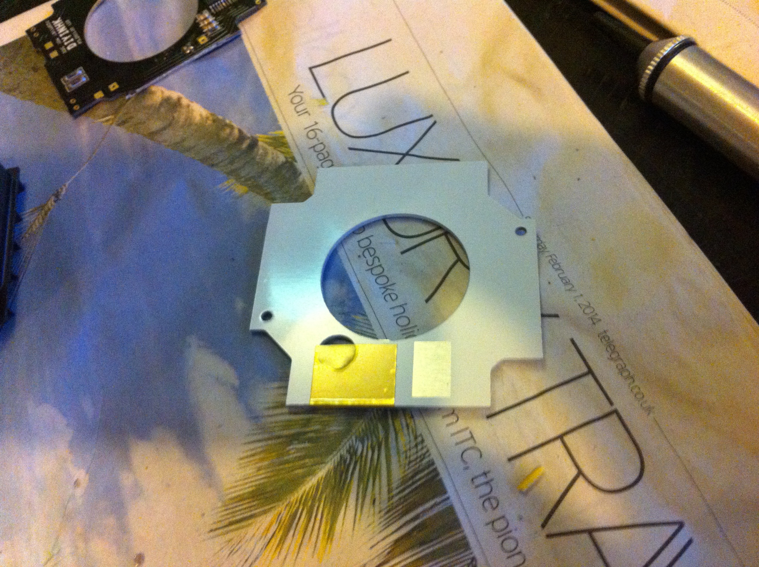
This plate is a heatsink provided within the kit from DIYINHK, the shiny portion is the exposed part which is arranged to fit over the Sanyo chip (use some thermal paste when mounting):
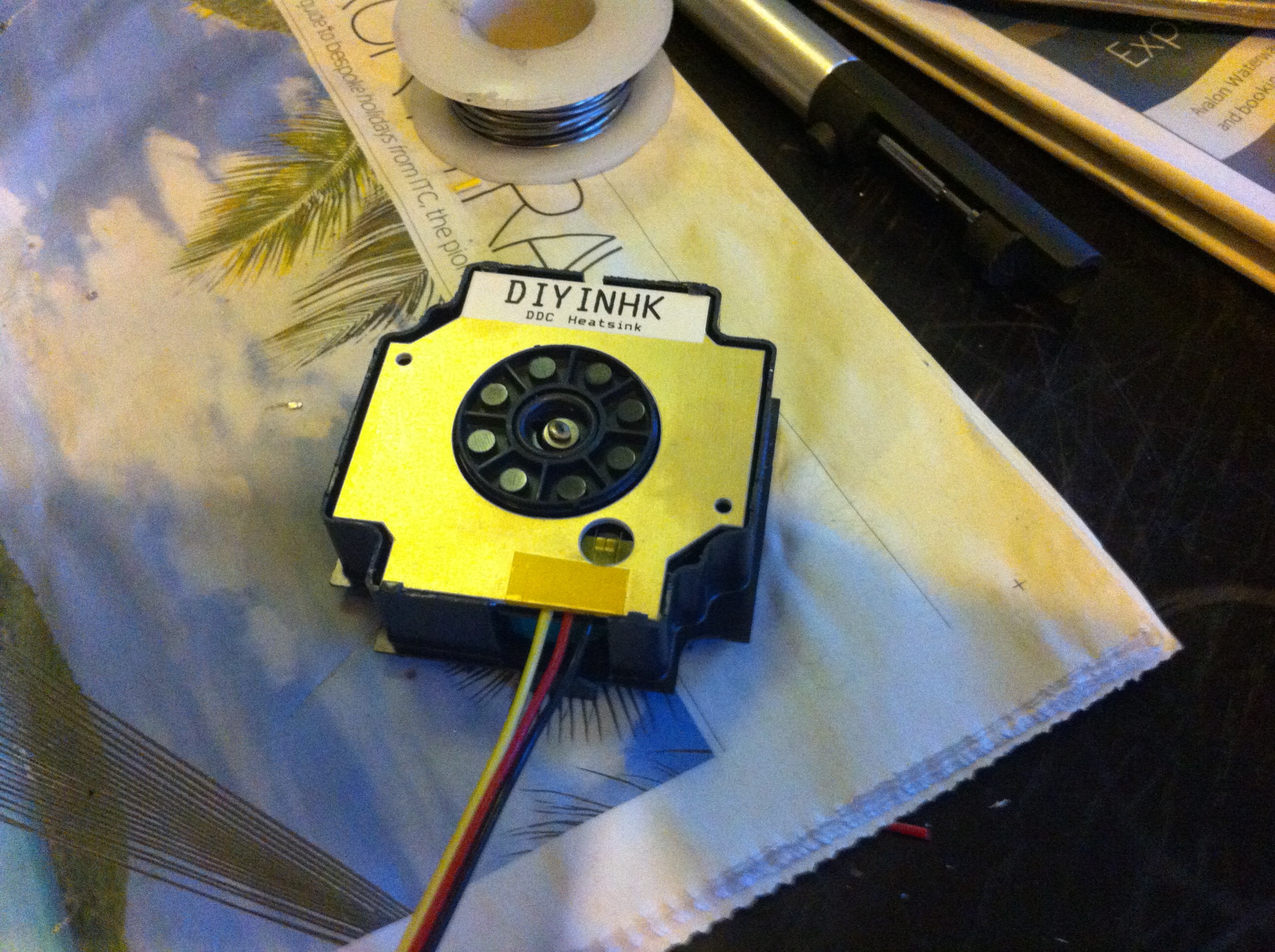
And with the heatsink in place:
Here is the pump being re-assembled now with the new control board and heat sink:
For those of you who like to see stuff being fitted, here is my video of the process of fitting the new controller PCB to the pump.
Once you have updated the controller board then you will need to decide how you want to use the pump. For instance, you can simple re-assemble the pump with the original volume control base and the original top and use it like that.
Alternatively you will probably want to use one of the after market pump tops or you might use them in a combined pump and reservoir system – there are lots of options out there.
If you decide not to use the extra little compartment with the springs then this is of course fine (after all, chances are you are using the pump in a system with a reservoir). Please note though, if you remove the spring compartment, you must also seal the hole at the base of the pump chamber. This can be done with silicone sealant, some epoxies etc, but I am a big fan of Sugru . This is a great product that moulds by hand, sticks to almost everything, is waterproof and dishwasher safe (!) and has many marvellous properties.
I bought six of the upgrade kits from DIYINHK and have used 5 of them on the G5 pumps I have here. At least two of them will be seeing service in my in house water cooled G5 conversions, others will simply get put to one side for a rainy day project. However, if after seeing this you think that doing an upgrade yourself may be a bit too difficult then drop me a line as I may be able to help!