In 2015 Macworld Magazine called these speakers “The best speakers ‘Apple’ ever made”.
The Apple Pro ‘eyeball’ speakers were introduced with the Digital Audio Power Mac G4 and mostly shipped with the iMac G4 – also known as the Sunflower or the Lampshade iMac.
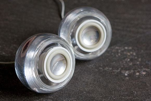
The design complemented that of the iMac G4 and they still look great today and have quite a following. But Apple effectively crippled the speakers so that they were only really useable in their original state with the iMac and could not be used as standalone speaker combinations or with a PC.
What’s the Problem?
To restrict them for use with the iMac or other compatible ( at the time) Apple computers, they were shipped with a weird looking 2.5mm jack plug connection with a cylindrical shield surrounding the 4 pole jack.

This cylindrical shield physically prevents the 2.5mm jack from being used with a 2.5mm socket. But that’s not the only way this jack differs from most – more of that later.
The second issue with these speakers is the wiring – what on earth is going on here?
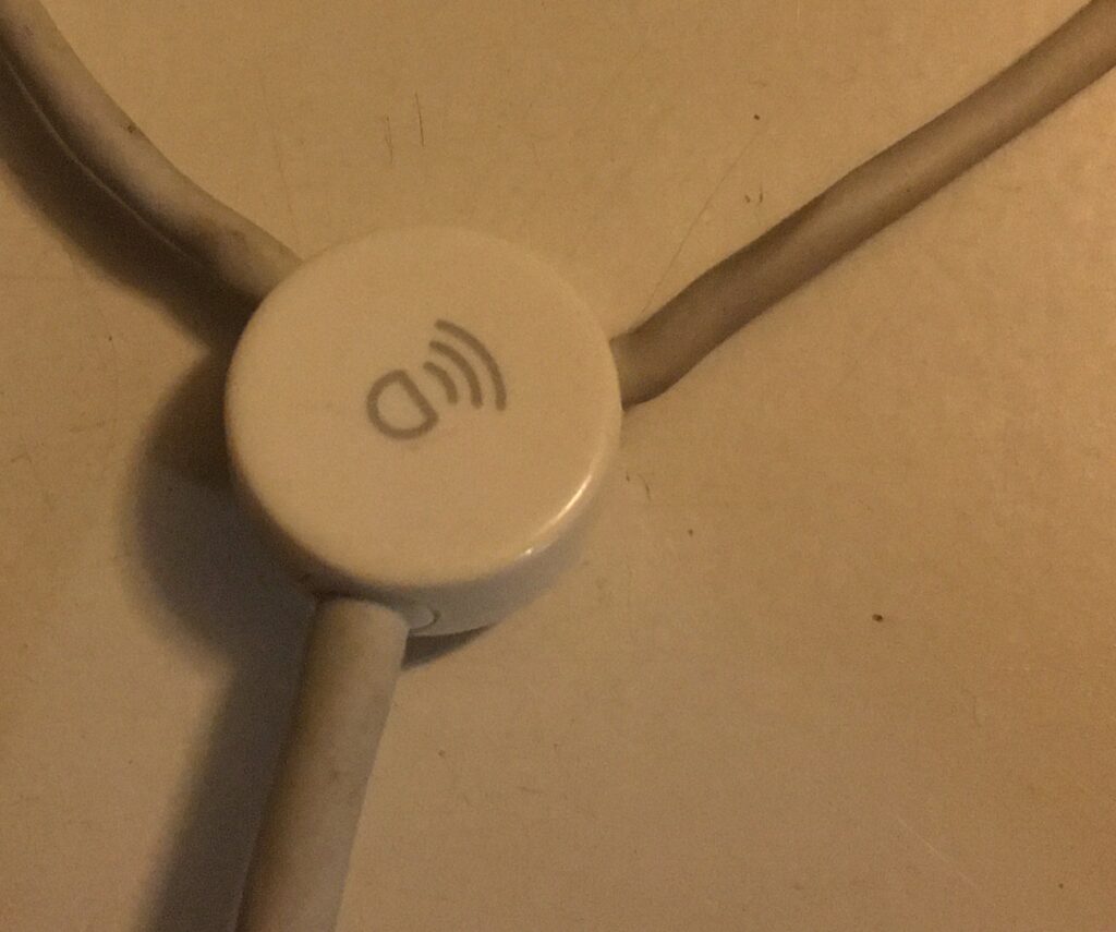

There’s a mysterious little circular blob in the junction of a Y connection – 6 wires went from the iMac to the circular blob and then 2 wires only per speaker ( as usual ) went from that blob to left and right.
Over the years there was a lot of speculation about the cylindrical shield and the circular blob. Some said the circular blob was an amplifier, others said it was some sort of disabling circuit so that audio could only pass to the speakers if the blob got an enabling signal from the iMac.
A contributor to Dremel Junkie’s Blog had sawn apart the blob circle and revealed that in reality there was some sort of EPROM in there connected to a red and a black wire.
This solved the basic mystery that in reality these speakers were just ordinary speakers and that the iMac simply had an onboard audio amplifier and was basically feeding an amplified stereo signal to the speakers. The absence of the correct output from the blob EPROM to the iMac’s internal logic board meant that the iMac knew that there were not any valid speakers connected and so it would not send the audio signal to the speaker.
The Simple Solution
The Blob is in the way, the connector is not standard. Let’s just cut the speakers free from everything and wire them up like ordinary speakers.
Just cut and strip the wires and hook them up to an amplifier.
Done. Problem solved….
But isn’t there a more elegant solution?
Investigations
Having come this far, I thought, let’s go one step further and actually determine once and for all the actual pinout of the proprietary 2.5mm jack plug itself and see if with a little modification these lovely speakers can be used in their ( almost) original state by using a universal 4pole 2.5mm jack socket.
I decided to completely free the wires at the speakers themselves to start my testing as I thought there might be some grouping together of earth wires etc and I also didn’t want my cheap multimeter to get confused by speaker impedance itself.
In reality it is quite easy to separate the drivers from the plastic ‘eyeball’ enclosure, 3 small screws at the front and then you just need to slacken off and remove the wire clamp at the rear. This clamp is the little circle at the back of the Eyeball and you just need to make it rotate counterclockwise ( i.e. unscrew) by using a small screwdriver in one of the three little indentations.
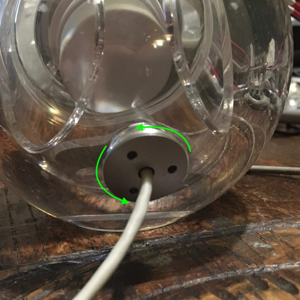
Actually I found the easiest way was to start the screwdriver in one indentation to get a tiny movement relative to the Eyeball enclosure and then switch the screwdriver to the next indentation to push a bit more and then to the third one etc. As soon as it starts moving this then becomes easy and it unscrews well enough. That allows you to pull more wire into the eyeball so you can get to the drivers themselves.
If you get up close you can see that the left speaker has white and blue wires and at the connection of the white you can actually see a little “+” (not the giant “+” in the picture I added that to the photo afterwards!), while the right hand speaker has brown and yellow wires, the yellow being “+”.
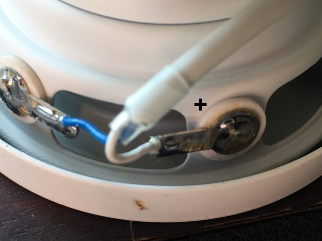
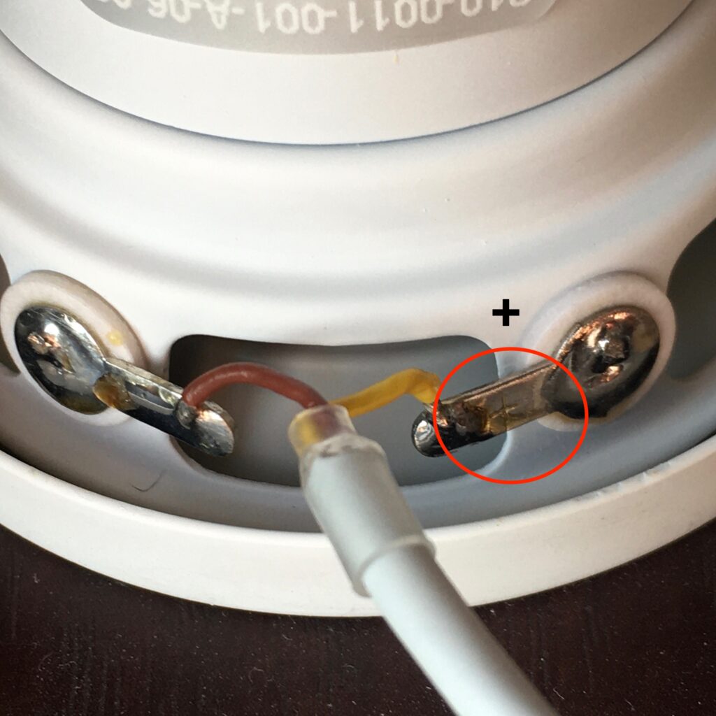
My next step was to unsolder all 4 speaker wires and hack off the cylindrical sleeve of the connector so I could test what connections were actually on the 2.5mm jack itself without there being any obstructions in the way of my multimeter.
The Hack and my chosen solutions
Here’s what I found:
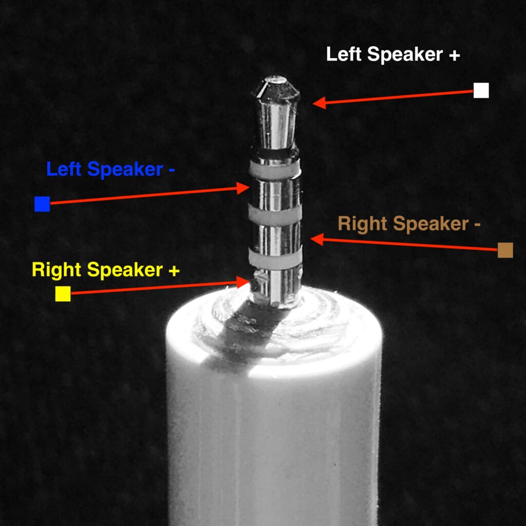
To my relief I found that the central post IS a standard 2.5mm jack size, with 4 poles ( connection areas). This is known as a TRSS type connector Tip- Ring – Shield – Shield. From the tip and working down we have: White ( Left speaker + ), Blue ( Left Speaker – ), Brown ( Right Speaker – ), Yellow ( Right Speaker + ).
The speaker negative terminals are not shared like in many more usual 3 pole audio jacks that would normally have Left “+”, Right “+” and Common “-” connections. The 4 pole type connections are usually associated with higher end audio and gives potential for what is known as a balanced audio connection. In balanced audio connections each speaker is fed with a twisted pair of signal wires and this twisting of positive and negative pairs gives signal protection ( shielding ) advantages.
The other advantage of it being a 4 pole connector with pairs of wires all the way from the connector through to each speaker is that they can carry more signal power without degradation ( as a doubling up of the current in the common negative would be a quality/power limiting factor if a 3 pin connection had been used by Apple).
So, while all the above is lovely for sound quality, it does still leave the problem that there is still the need for getting an amplified audio signal to our newly revealed 2.5mm jack plug.
Even if the speakers could be driven through a normal headphone socket there is no point in plugging this 2.5mm jack plug into the more common 4 pin 2.5mm to 3.5mm Audio or AV adapters as they are NOT for balanced connections instead they have a connection pattern of: Tip-Ring-Shield-Shield: Left +, Right +, Ground , Mic ( if audio ) /Video ( if Audio/Video cable). So putting our configuration into one of those adapters you’d only get single ( left) channel audio anyway.
So instead lets just take a female 2.5mm 4 pole jack socket and wire that up to our amplified audio. A little bit of searching and I found a good match by finding a 4 pole 2.5mm socket – reference MJ-068H and then some more multimeter work. I have taken the data sheet for this socket and annotated it and also added some pictures for how to wire it correctly.

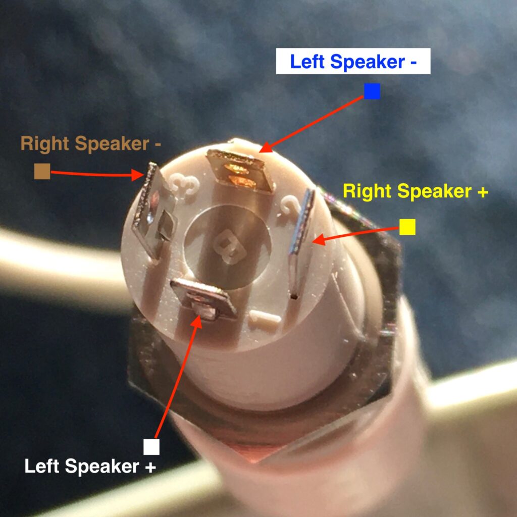

The 4 terminals of the MJ-068H socket can now have wires soldered to it ( in twisted pairs ideally!) and linked to the output of an audio amplifier.
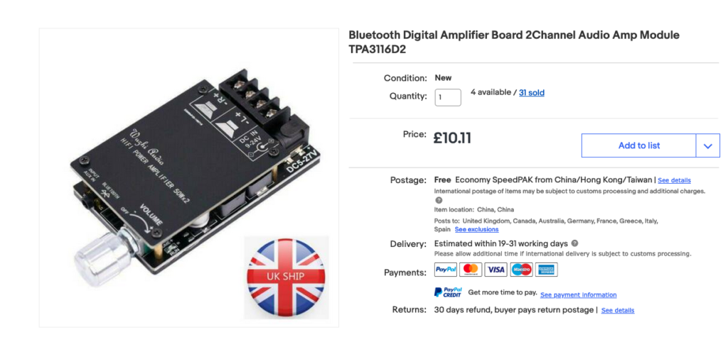
To make a really nice job of this, then these speakers and their full connection parts ( minus that cylindrical barrier) can form part of a computer case mod or a simple desktop amplifier mod. At the moment I have mine wired up to a bluetooth amplifier like this one:
Summary
So after all this, here’s all you really need to do and to know.
- Remove the outer cylinder ring of the 2.5mm jack plug. You can either do that by careful sawing with a hacksaw or by using a Dremel on very slow speed and taking your time going around and around the edge of the jack plug – either way be very careful NOT to damage the central 4 pole connection.
2. Buy a 4pole 2.5mm jack socket ( e.g. the MJ-068H socket) and use my annotated pictures and pdf spec sheet to make your left and right speaker connections and connect to an amplified audio source ( such as the Bluetooth amplifier I mentioned or whatever else ).
3. Sit back and enjoy the sounds.
Hope someone finds this useful!
