Xserve RAID Case Interior planning
A major part of this exercise is planning out the interior part of the case behind the hard drives and coming up with a nice backplate.
Previous attempts at modding interior space by others largely focus on fitting a mini ITX board. As far as I am aware, no-one has actually completed a conversion using a standard height IO shield and an ATX motherboard.
Alex is clear in his brief to me that he does not want an ITX board, or to have a half height IO shield. but that maybe a micro ATX board is okay. I sense though that his preference is for full ATX so that can use a lot of PCI-e cards.
What do we have to work with?
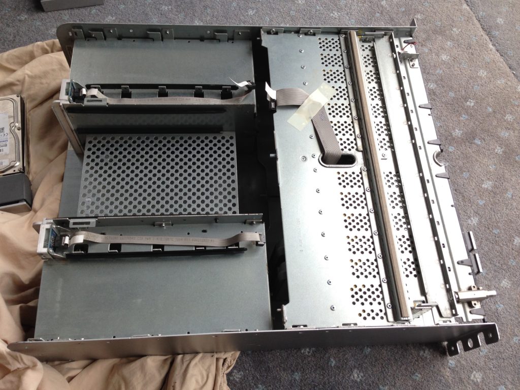
I took out the removable items from the case back and lifted the lid.
To the right – the hard drive cage. To the left – the modular framework. The modular framework holds the original power supplies, controllers etc.
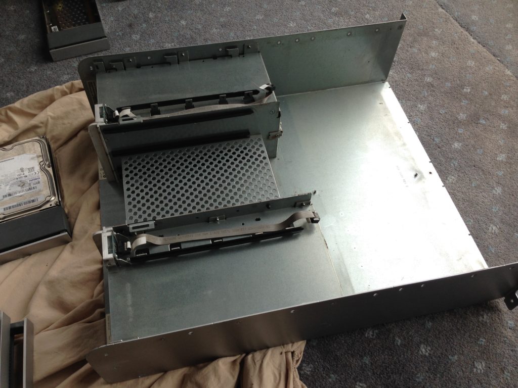
Here is what it looks like with the hard drive cages removed:
The framework is secured by lots and lots of rivets – remove these with a 3mm drill bit to clear the case of everything.
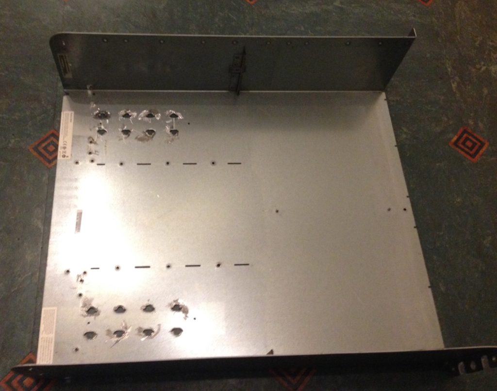
Here it is – everything out!
In this photo you can see that as well as stripping the framework out I have also dremmelled off all the protrusions in the rear part of the case to make it easier to mount a motherboard tray into the area. This takes a surprisingly long time…copper strips and extra rivets to remove as well as protruding case vents.
Backplate planning
The first task is planning the backplate. Space available is tight.
The height inside the box is just about 126mm. As my standard IO shields are taller than this, the prospects are not ideal….
The width of the case is 440mm and this at least is at first glance promising. However, a full ATX motherboard is 305mm wide and a standard ATX PSU is 140 mm wide….so even the raw numbers show that the case interior is not likely to support this.
Options come down pretty much to either: mATX board plus standard ATX PSU OR full ATX motherboard plus SFX PSU.
An SFX PSU such as those made by Silverstone or by Corsair comes in at just 125mm by 63.5 mm. These supplies are not terribly loud and offer good power options.
So it looks like full ATX mobo plus an SFX PSU will probably work for the backplate.
How to attach the backplate?
The Xserve RAID does not have a backplate. Instead it is built around a framework with modular items which plug-in and out of it.
Removing the original internal framework removes a lot of case weight. It also deprives the case of a significant amount of stiffness.
Clearly when trying to integrate standard PC components in such a tight space producing a modular backplate for this machine is not easy. The question is how do we attach our backplate design when there is nothing obvious to secure it to?
The case, when cleared out, does have some ready-made holes in the side panels near the back. So a backplate with a pair of folded end flaps seems a logical way to go. When folded at 90 degrees these flaps will secure the backplate to the existing case holes.
Our new backplate must be stiff enough to support our power supply. It must also not flex significantly when plugging in or removing power cords, cables and accessories.
The Backplate Design
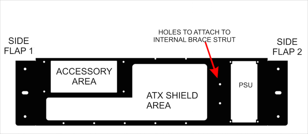
My current design [and for which I am awaiting the arrival of a prototype] includes a very strong right-angled brace strut. This strut is actually a shelf support and is more than enough to hold the back plate in place. The strut attaches to the case floor and supports the new backplate between the motherboard and the power supply.
This first design with three areas of attachment will hopefully work. However, the truth about prototyping is that we rarely get it right first time! Already I have some more thoughts on how to improve it.
Design Pros
Good things about this design are:
- It will support motherboard sizes from ITX up to ATX.
- A vertical power supply position means a maximum floor area available internally for the case.
- The ”accessory area” gives multi use capability.
Placing the motherboard to the extreme left of the backplate means that when using an ITX or mATX board, instead of an ATX mobo, then extra useful interior space opens up. To maximise use of this space a false floor can be provided. The false floor can cover over the unused ATX motherboard supports and allow an extra accessory or more cooling.
The accessory area could be used for a simple inlet/outlet grill. Alternatively it could be used for fans, as a cooler intake/outlet, or even as an alternate PSU mounting. A specialised plate could be cut to accommodate changes without needing to supply a totally new backplate.
Design Cons
The backplate is shorter than my IO shields. I will cut the top fixing edge of the shield down so that it will fit. However, this is an indicator that there is minimal headroom for PCI-e cards. For a discrete GPU headroom is severely limited -so another fix for that is required. However, for a server implementation internal graphics is perhaps all that is needed.
There is very little space on the backplate for cooling. This is an issue with any backplate capable of taking an ATX motherboard.
Cooling
To mitigate the lack of air inlets/outlets on the backplate there are design choices. These choices are:
- Choose low power components;
- Include extra air intakes/outlets on other areas of the case;
- Use a smaller motherboard size than ATX and use the extra available space on the backplate and the interior to provide extra cooling.
I will explore the design choices in a future post. The next post will be all about motherboard placement when I finally get my backplate to play with.


